JTAG USB BLASTER DRIVER DOWNLOAD
| Uploader: | Kagajin |
| Date Added: | 18 July 2013 |
| File Size: | 66.11 Mb |
| Operating Systems: | Windows NT/2000/XP/2003/2003/7/8/10 MacOS 10/X |
| Downloads: | 78963 |
| Price: | Free* [*Free Regsitration Required] |
Must be set to indicate byte-shift mode. But the cheap clone runs TCK at exactly double the speed of the Terasic, and both devices only use a flimsy, cheap flat cable. If Bit 6 was.

TMS bits to be written bit The suffix is really different, with 6 clock clocks but also ubs fast clock group in between. A fast clock group sets the clock at 12MHz instead of 6MHz.
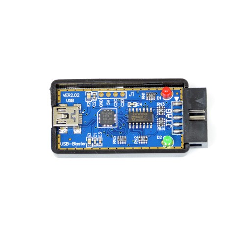
Mini USB Blaster JTAG Programmer for Altera, FPGA, CPLD
In addition, there are roughly 3 idle cycles between a fast clock group. It's not jfag it's broken: LSB of the first byte after the header byte will appear first. A really interesting difference is in the spacing between fast clock groups: We have a prefix with 8 slow clocks, but in between the second and the third slow clock, there's a signal fast clock group.
Up to 64 bytes can be combined in a single USB packet.
OpenOCD: usb_blaster.c Source File
In the middle we have the expected 16 fast clock groups. For the overview, look at the upper set. Zooming in on the slow clocks, we see a clock frequency of kHz.
The Terasic doesn't have that problem: My money is on the clock speed: This function provides a "bit sequence" indicating what has to be done with TMS during a sequence of It may be that 12MHz is really just pushing things too much. If we ignore for a second that the cheap clone doesn't work on this particular board, the biggest consequence of the chapeau clone is that bulk transfers are much slower: What remains is the question about why the cheap clone doesn't work.
About Us Contact Hackaday. Use this macro to access the arguments for the command being handled, rather than accessing the varia For the cheap clone, the spacing is huge: Yes, mtag it Cancel.
There are 3 major sections: Define the number N of following bytes.

This is the first transaction that travels over the JTAG cable when you issue the "nios2-terminal" command. The most important signal here is TCK, in yellow.
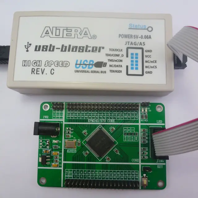
Using an Altera USB-Blaster ? Read this first.
It looks like the cheap clone is able to squeeze out bits really fast, but there's quite a bit of software overhead in processing the next byte in the USB packet. Must be zero see byte-shift mode above. Use this macro to access the name of the command being handled, rather than accessing the variable di Go to the documentation of this file.
When you zoom in on the slow clock cycles, you can measure a TCK frequency of kHz: I was supposed to work on getting the SiI up and runningbut UPS delivered a nice package today: We see a similar pattern, but interestingly enough, it's not the same. If set, you will receive a byte indicating the state of TDO.

Comments
Post a Comment